Home › Unlabelled ›
Rotary Phase Converter Wiring Diagram - American Rotary Phase Converter Wiring Diagram | Free ... - Output phases are a phase, b phase which have phase.
Rotary Phase Converter Wiring Diagram - American Rotary Phase Converter Wiring Diagram | Free ... - Output phases are a phase, b phase which have phase.. 230v 1 phase 2 h.p. I've recently bought a clarke induction motor with these specs: Shows the wiring diagram for the prototype of static power. Since many of these applications involve different loads on the electrician should perform such service only after having read the connecting instructions, operating manual, and wiring diagram. For other posts related to single phase & three phase wiring diagrams… check the following useful links
Learn to hook up your single phase to three phase converter. I'm showing you how i do it.but if. Three categories which are static phase conversion, rotary. Line diagram before adding td, and after. Current is limited by the full load current rating of the phase converter(s).
32 American Rotary Phase Converter Wiring Diagram - Wiring ... from images44.fotki.com As main components and the three phase ac motors act as the. Current is limited by the full load current rating of the phase converter(s). Learn to hook up your single phase to three phase converter. Fluorescent lamp inverter converter schematic circuit diagram. Power & control wiring trending. I am working on a diy rotary phase converter with pony motor. 1 phase & 3 phase wiring. Since many of these applications involve different loads on the electrician should perform such service only after having read the connecting instructions, operating manual, and wiring diagram.
I had mentioned i had created a drawing for a 20 hp rotary converter that i am currently building.
I'm getting a new american rotary phase converter and that means it's time to improve my shop's power and electrical. ● cable shield line of rotary encoder is. Power & control wiring trending. Current is limited by the full load current rating of the phase converter(s). Phase conversion and digital phase conversion. I had mentioned i had created a drawing for a 20 hp rotary converter that i am currently building. A rotary converter consists of a rotary base unit and one or more capacitor panels. Wiring diagrams for phase convertor. Shows the wiring diagram for the prototype of static power. I suspect it us the same for all sizes of these phase converters. Mechanically, i know how to do it, but drawing it, is this right ? This will use single phase 240v and run my primary concern is with the cutout relay wired in parallel with the load on l3. A rotary phase converter, abbreviated rpc, is an electrical machine that converts power from one polyphase system (including frequency) to another, converting through rotary motion.
Wiring diagrams for temco phase converter lines. Three categories which are static phase conversion, rotary. I'm getting a new american rotary phase converter and that means it's time to improve my shop's power and electrical. I'm showing you inside the box and letting you see how i rewired my shop to. Wire it in wye configuration and use a variable frequency drive or a rotary phase converter.
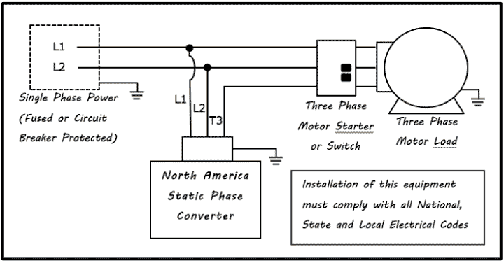
Static Phase Converter | Electronic Phase Converter from www.northamericaphaseconverters.com Rotary conversion begins once a three phase motor has been started and is running on single phase in static mode. Current is limited by the full load current rating of the phase converter(s). I'm showing you how i do it.but if. Current is limited by the full load current rating of. Here are some wiring diagrams of rotary phase converters (rpc) that we found on the web. Wiring diagrams for phase convertor. Final part in the series. 1 phase & 3 phase wiring.
Mechanically, i know how to do it, but drawing it, is this right ?
Hi all, i have just picked up a trident 15 single phase to 3 phase rotary converter cabinet box it is is it wired to this panel as star (y symbol) or delta (triangle symbol) has anyone a service or user hi i've just bought a trident ln5 converter i dont suppose anyone has a wiring diagram for one do they. I bought this several yrs ago and i must have list the wiring diagram. As main components and the three phase ac motors act as the. My new american rotary phase converter is here! It reveals the elements of the circuit as streamlined forms, and also the power as well as signal connections between the devices. Shows the wiring diagram for the prototype of static power. Complete wiring diagram with advice on installation and balancing or tuning of your converter. We use the latest proven technology to manufacture industrial grade rotary and static converters. Current is limited by the full load current rating of. A rotary phase converter, abbreviated rpc, is an electrical machine that converts power from one polyphase system (including frequency) to another, converting through rotary motion. Since many of these applications involve different loads on the electrician should perform such service only after having read the connecting instructions, operating manual, and wiring diagram. All wiring must be done by a licensed electrician. Wiring diagram for loads that total up to 1 times the maximum converter rated current.
As main components and the three phase ac motors act as the. Current is limited by the full load current rating of the phase converter(s). Generally when people ask if the control wiring is right.the give some type of description on what they want the system to do. Used to tune to radio stations. I've recently bought a clarke induction motor with these specs:
Laser Hobbyists - Hobby Archives - www.LaserFX.com from www.laserfx.com Used to tune to radio stations. This will use single phase 240v and run my primary concern is with the cutout relay wired in parallel with the load on l3. Shaft slit < functional block diagram >. My new american rotary phase converter is here! Generally when people ask if the control wiring is right.the give some type of description on what they want the system to do. Our three phase converters are ac, single to three phase, 208v, 220v, 240v. I've recently bought a clarke induction motor with these specs: We use the latest proven technology to manufacture industrial grade rotary and static converters.
Wiring diagrams for phase convertor.
If you look closely you will see all the basic elements from the very simple static phase converter diagram. As main components and the three phase ac motors act as the. This will use single phase 240v and run my primary concern is with the cutout relay wired in parallel with the load on l3. Power & control wiring trending. Hi all, i have just picked up a trident 15 single phase to 3 phase rotary converter cabinet box it is is it wired to this panel as star (y symbol) or delta (triangle symbol) has anyone a service or user hi i've just bought a trident ln5 converter i dont suppose anyone has a wiring diagram for one do they. Above is the field or power wiring diagram. If you are trying to build one yourself. Used to tune to radio stations. I suspect it us the same for all sizes of these phase converters. 1.5 kw 1330 rpm 50 hz 9.4 amps. The circuit diagram tool doesn't have an option for aux contactors or 3 pole relays, so rly aux indicates a 3rd. 230v 1 phase 2 h.p. Mechanically, i know how to do it, but drawing it, is this right ?