Home › Unlabelled ›
Circuit Diagram Of Doorbell / 2 Tone Door Bell Circuit Diagram Electronic Circuit Projects Doorbell / The um3481a is designed to play the melody according to the previously programmed information and is capable of generating 16 songs with 3 instrument.
Circuit Diagram Of Doorbell / 2 Tone Door Bell Circuit Diagram Electronic Circuit Projects Doorbell / The um3481a is designed to play the melody according to the previously programmed information and is capable of generating 16 songs with 3 instrument.. On each press it will give a new tone which will continue till the melody is over. Familiarize yourself with the four most common doorbell push button, chime, and transformer circuits by taking a look at the diagrams below. The um3481a is designed to play the melody according to the previously programmed information and is capable of generating 16 songs with 3 instrument. There are many versions of this ic are available, each version has a different melody programmed by the The wireless doorbell transmitter and receiver circuit are incorporated below:
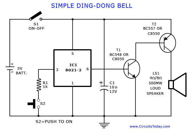
The circuit uses the popular melody generator ic um3481. It gives eight melodious tunes for 2 minutes. The working principal of the circuit doorbell is simple. The bell, a button mounted at the door, and a battery somewhere in between the two. On each press it will give a new tone which will continue till the melody is over.
Covid 19 Coronavirus Doorbell Arduino Project Hub from hackster.imgix.net The bc547 transistor along with the associated preset and the 100uf capacitor form a simple delay off timer circuit, where the preset and the capacitor determines the delay for which the sound output may be sustained once the indicated push button is pressed. The circuit is actually radiating from the printed track of the tank circuit. A buzzer is used to make a sound whenever the button is pressed. Doorbell parts section below for more information). It shows the elements of the circuit as simplified shapes, and also the power and also signal links between the gadgets. The wireless doorbell transmitter and receiver circuit are incorporated below: Wiring diagrams for ring video doorbell pro setup if you're in the process of setting up multiple ring video doorbell pros, internal doorbells, and transformers, the following wiring diagrams may help. Circuit diagram and explanation above figure shows the circuit diagram for doorbell.
There are many versions of this ic are available, each version has a different melody programmed by the
The battery is the weakest link here and should be the first place to look for trouble. The circuit uses the popular melody generator ic um3481. It shows the elements of the circuit as simplified shapes, and also the power and also signal links between the gadgets. Wiring for a doorbell transformer and two buttons. The working principal of the circuit doorbell is simple. The circuit given below is a modified version of the melody generator circuit, whose link is given above. Circuit diagram and explanation above figure shows the circuit diagram for doorbell. The circuit for the musical doorbell can be seen below and is relatively simple. A conventional doorbell has wires that connect the chimes or bell to the button and transformer, which converts standard power to low voltage. There are many versions of this ic are available, each version has a different melody programmed by the A buzzer is used to make a sound whenever the button is pressed. Here low voltage ac is applied to the trigger pin 1 through r1 and d1. Doorbell push buttons don't have a positive and negative.
In parallel with the doorbell switch, s1, is a 1n4001 diode and a 12 volt 60ma bulb. On each press it will give a new tone which will continue till the melody is over. The battery is the weakest link here and should be the first place to look for trouble. There are many versions of this ic are available, each version has a different melody programmed by the The circuit is too simple and battery operated it uses the popular melody generator ic um3481.
Simple Doorbell Circuit Download Scientific Diagram from www.researchgate.net The circuit for the musical doorbell can be seen below and is relatively simple. Doorbell parts section below for more information). The sounding device that produces a ring, or chime or other type of sound when someone pushes the doorbell button. The sound is stored in the ic as bits, as in a rom. The circuit is too simple and battery operated it uses the popular melody generator ic um3481. Wiring diagrams for ring video doorbell pro setup if you're in the process of setting up multiple ring video doorbell pros, internal doorbells, and transformers, the following wiring diagrams may help. Circuit diagram and explanation above figure shows the circuit diagram for doorbell. Wiring for a doorbell transformer and two buttons.
Here we can see that first 555 timer ic is configured in monostable mode, means it will go high and low only once if triggered with trigger pin 2.
Other connections are shown in the circuit diagram. It shows the elements of the circuit as simplified shapes, and also the power and also signal links between the gadgets. The working principal of the circuit doorbell is simple. The diagram above depicts the proposed musical door bell circuit, the various stages may be understood with the following explanation. The wireless doorbell transmitter and receiver circuit are incorporated below: Door chime wiring circuit diagram entry diagrams home to install a doorbell do i need digital adapter how wired works hometips schematic led understanding systems 1 2 full tutorial amp for bell can ring by itself reasons phone legrand 240vac 641728 built household doorbells nest o without new nutone musical 16 of. Single doorbell push button with a single chime. Here low voltage ac is applied to the trigger pin 1 through r1 and d1. Here we can see that first 555 timer ic is configured in monostable mode, means it will go high and low only once if triggered with trigger pin 2. The circuit uses standard 2 wire doorbell cable or loudspeaker wire. It gives eight melodious tunes for 2 minutes. A buzzer is used to make a sound whenever the button is pressed. The circuit of the wireless bell shown here is easy to built and using only few easy to find low cost components.
Other connections are shown in the circuit diagram. As illustrated in the above diagram, the parts of an old doorbell circuit include: The diagram above depicts the proposed musical door bell circuit, the various stages may be understood with the following explanation. Capacitor c1 and resistor r2 are the oscillation components. The circuit is too simple and battery operated it uses the popular melody generator ic um3481.
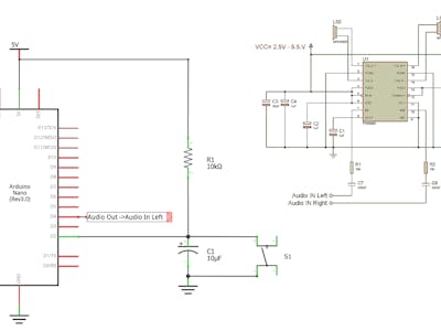
Tone Generator Circuit Simple Calling Bell Circuit from www.circuitstoday.com A um66 melody generator is connected at the output of the receiver circuit which will be activated when the receiver circuit receives signals from the transmitter. A conventional doorbell has wires that connect the chimes or bell to the button and transformer, which converts standard power to low voltage. Melody generator using um 66 door bell circuit using ne555. The bt66t is an easy to use little melody generator ic, mainly used in circuits where a melody has to be played as a notification for the user. Either terminal of the push button can be mounted to the red or white wires shown in the diagram (ref. As illustrated in the above diagram, the parts of an old doorbell circuit include: Other connections are shown in the circuit diagram. This musical doorbell circuit uses um3481 a series ic.
One ring video doorbell/two internal doorbells.
The bc547 transistor along with the associated preset and the 100uf capacitor form a simple delay off timer circuit, where the preset and the capacitor determines the delay for which the sound output may be sustained once the indicated push button is pressed. It shows the elements of the circuit as simplified shapes, and also the power and also signal links between the gadgets. The um3481a is designed to play the melody according to the previously programmed information and is capable of generating 16 songs with 3 instrument. The circuit uses the popular melody generator ic um3481. The diagram above depicts the proposed musical door bell circuit, the various stages may be understood with the following explanation. The bell, a button mounted at the door, and a battery somewhere in between the two. The battery is the weakest link here and should be the first place to look for trouble. The circuit given below is a modified version of the melody generator circuit, whose link is given above. Older systems may be 6 or 8 volts, and newer ones are 12 to 14 volts for bells and buzzers and 16 volts for chimes. The sounding device that produces a ring, or chime or other type of sound when someone pushes the doorbell button. This musical doorbell circuit uses um3481 a series ic. Here's an interesting circuit of a wireless door bell/buzzer for electronics students and hobbyists. Apart from the rf modules, only a 555 timer …